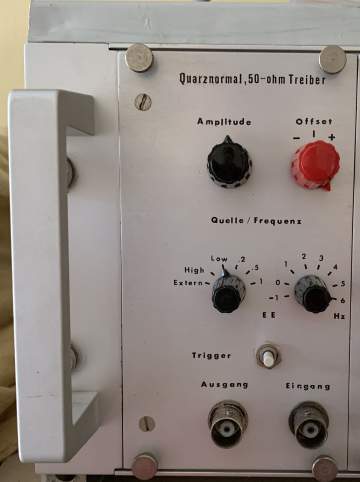
Square Wave Generator
Summary/Usage
This device is my DIY square wave generator. It can be used for
general purpose measurements in the electronics lab.
Today I use it mostly to test power supplies together with my simple
electronic load.
Functional Description
I designed for the following features:
- Analog Rotary switches for frequency control
- Analog potentiometers for output voltage and offset voltage control
- Push button switch with "click" and gold contacts
- 50 Ohms impedance output jack.
Performance Specs
- 0.1 Hz - 1 MHz, in steps 1-2-5, crystal oscillator accuracy
- Additional always low or always high output with debounced low to
high and high to low push button action
- Output 10 Vpp max. with 50 Ohm impedance
- 15 ns rise, 10 ns fall time
- Adjustable DC offset
- Separate output jack with TTL compatible signal
Design
- 1 MHz crystal oscillator using one CMOS inverter (well it is a
single 74HC00 NAND gate)
- Classic TTL 1:10 divider chain using 74LS90 decimal counters plus
1:1, 1:2 and 1:5 dividers, the later also 74LS90
- Discrete transistor output stage using a switched current source
delivering into a 50 Ohm resistor
- Additional adjustable transistor current source to achieve
adjustable offset voltage
Schematics (SVG files)


LTspice and Kicad files
LTspice and Kicad files can be found in the ZIP-Archive.
Mechanics
Front View

Legal Notices
Copyright
Copyright (C) 2020-2023, by Dr. Thomas Redelberger, redetho(at)gmx.de. All
rights reserved.
I do not intend to offer/sell this!
I publish here the electrical schematics and the mechanical design,
such that you could build your own device. I put all the files of this
project under the GPL2 open-source license. See the file
COPYING.TXT. This is hence open hardware.
Disclaimer
Actual construction of the circuit requires a significant knowledge
of electronic circuit design and construction beyond what is presented
here. The author, Dr. Thomas Redelberger, does not warrant
operability, reliability, suitability or safety of any of the
circuits. Anyone who constructs and/or uses these circuits accepts all
responsibility for their operation and safety.
