
You might want to use your PC sound card as a simple oscilloscope.
I found that the electrical characteristics of the line-in input of my PCs were such that you do not want to use it as such to do measurements: low input impedance and high capacitance compared to a standard oscilloscope input.
This is why I designed a simple pre-amplifier to rectify this.
I had the following design objectives:
However, the circuit does not lift main limitations of sound card based oscilloscopes:
The proposed pre-amplifier shall go in-between the device under test and the sound card line-in input.
This will also have the advantage that input jacks can be standard BNC, while the connection to the sound card uses standard 3.5 mm audio cable. BNC allows to use standard test wires and probes such as oscilloscope 1:1 probes. These use low capacitance cables which can be important to not load the device under test too much. Such probe cables are usually only 1 − 1.2 metres long.
The pre-amplifier will also protect the PC sound card from overly large voltages. However, the proposed design of circuit and case does not allow for use in high voltage, high current and mains voltage environments. You have been warned!
The pre-amplifier circuit is a classical source follower using an n-channel JFET (see https://en.wikipedia.org/wiki/Common_drain). JFETs usually cover high bandwidth.
The circuit design is similar to what has been used as a first Y-amplifier stage in oscilloscopes since a long time. It has voltage "amplification" of approximately 1, has very high input impedance and low output impedance. It can thus drive relatively long cables. Thus, the cable between the PC sound card line-in input jack and the pre-amp. can be 2 − 3 metres long without negatively affecting the performance. Good quality audio cable with 3.5 mm plugs are OK.
I included an optional 1/4 attenuation circuit to increase the voltage range. It can be activated by a switch per channel. Alternatively, − or in addition − 1:10 oscilloscope probes can be used. Thus, various voltage ranges can be covered with optimal dynamic range.
The JFET is a standard BF245A which should do the business. Please note that the "B" or "C" suffix types might work as well, but that has not been tested. The main limitation is the battery voltage minus the forward current of the "On" LED, as this limits the useful input and output voltage range.
There are two identical circuits per channel, i.e. one source follower per input channel. Mechanically there are two separate BNC jacks for the two input channels. On the output side, the two channels share the same 3.5 mm audio stereo cable from the pre-amp. to the sound card.
I use a standard 9 volt block battery to power the device. The operating current is so low, that battery life should be months when used occasionally. A LED signals the device is switched on. The LED is powered by the quiescent current of the two source followers, rather than putting the LED directly after the on-switch with its own current limiting resistor. This saves some power at the expense of useful input and output voltage range. In effect, the LED makes the battery look like having 2 − 3 volts lower voltage, depending of the LED type. This is not a limitation as the circuit still has a larger input and output voltage range than the two sound cards I had been using.
The exact LED type is pretty irrelevant. I went for a standard 3 millimetres yellow LED with 2,000 mCd brightness.

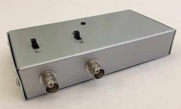
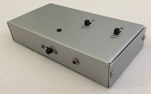
I chose a flat aluminium case. I did not use all the available space as I might add another circuit to the case later.
There are quality BNC jacks and a 3.5 mm jack to plug a standard line-in cable to the sound card. The on-switch and the attenuation switches are sliding switches I had available. Normally I would choose rocking switches but this is a matter of taste anyway.
The case is used upside down to allow to wire directly to the jacks and switches. I used no printed circuit board but some vero-board as the circuit is quite simple.
I do not intend to offer/sell this!
I publish here the electrical schematics and the mechanical design, such that you could build your own device.
All content including diagrams and photographs are copyrighted (c)
2017-2024, by Dr. Thomas Redelberger,
redetho gmx.de. All rights reserved.
Actual construction of the circuit requires a significant knowledge of electronic circuit design and construction beyond what is presented here.
The author, Dr. Thomas Redelberger, does not warrant operability, reliability, suitability or safety of any of the circuits.
Anyone who constructs and/or uses this circuits accepts all responsibility for its operation and safety.
In particular the circuit proposed here is not suitable for any high voltage, high current or mains voltage operation. You have been warned!

 Home
Home Projects
 Music Electronics
 Electronic Load