
Zur deutschen Version.
This device is a simple do-it-yourself electronic load. For example it can be used to test power supplies.
The following lab devices are necessary in addition to trelload:
The trelload electronic load device has the following features:

In a static measurement, you demand from your device under test (DUT) to deliver a constant current. The use the electronic load in this scenario, you need to connect an adjustable control voltage to the electronic load, for example from a lab power supply. The current to be delivered is in the order of a few 10s of mA.
Before you start, you need to choose an appropriate emitter resistor of the electronic load (R2 - R5 in the schematic). The emitter resistor shall match the maximal output current of the DUT. Example:
Caveat: The driving voltage always needs to be below the DUT output voltage. Otherwise the base-collector diode of the transistor will conduct. The base resistor R1 means to limit the base current to protect the transistor.
Be aware that the DUT output voltage may sharply decrease at high load currents due to built in over-current protection circuitry. In that region, you might want to chose a lower emitter resistor, to make sure the driving voltage always stays below the DUT output voltage. In the specific example above, you could choose 2 Ω. These could be achieved by connecting two 4 Ω resistors in parallel.
You could measure the dependency of the DUT output voltage from the load current using simple resistors. But you needed different resistors for that. These resistors also need to stand the power to dissipate. Instead, using the proposed electronic load you can easily adjust the load current and measure the resulting DUT output voltage.
The following schematic shows how to connect the DUT, the trelload electronic load and the other test equipment:

You would start with a lab supply voltage V2 of 0 V and increase it step by step, while you record the two voltage readings E1 and E2 from the two multi-meters.
As stated above, you can calculate the load current from voltage VE2. Hence you can record the load current together with the DUT output voltage VE1 in a table. From the results you can calculate the load regulation.
In important attribute of a power supply is its efficiency, i.e. how much power is drawn from the 230 V or 110 V mains (primary) side for a specific load on the output (secondary) side. The test set-up above can easily expanded to measure efficiency.
The following schematic shows the power meter that is added on the mains side of the DUT:

You measure like above, but in addition you record for each load current the power requirement on the primary (110 V or 230 V mains) side of the DUT. The power delivered on the output side of the DUT you calculate by multiplying the output voltage with the load current. The efficiency can then be calculated by dividing the delivered power by the primary power. Most often you will find that the efficiency depends on the load current.
When you measure the output voltage using an oscilloscope, you can determine the output voltage ripple. The ripple can also depend from the load current. The Y-input of the oscilloscope has be be switched to AC-coupling.
Usually, the following cases are relevant:

You measure and records the output voltage using the oscilloscope, while you increase the load current step-by-step.
I had various DUTs, where ‑ surprisingly ‑ the ripple was especially high for intermediate loads, much below their maximum load current capability.
The static measurements described above yield the DUT's behaviour for a constant or slowly varying current. Using the electronic load, you can also measure the dynamic behaviour of the DUT for fast changes of the load current.
Instead to a lab power supply, you connect the control input of the electronic load to a pulse or function generator. The generator shall have an output impedance low enough
Most generators have 50 Ω output impedance. That will do.

To measure a fast load current change from zero load current to specific load current, you set the pulse generator to a rectangular wave form output and set the amplitude to jump to a voltage that corresponds to the wanted specific current. If the pulse generator as an adjustable offset voltage, you can also observe DUT behaviour for switching between two defined load currents.
The dynamic test will reveal
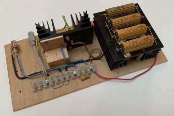
I mounted the trelload parts on a piece of scrap wood. Both the transistor and the resistors are mounted on heat sinks. However the set-up is not suitable for continous operations.
I used insulated copper wires that go to posts which fix the wrires using screws. The DUT is connected using a socket for a "hollow" barrel plug, because many power supplies use these. For the control input I use a BNC-Connector, because my pulse generator can also generate fixed voltages. This is convenient, because I do not need a separate lab power supply for the static tests and I usually do the dynamic test anyway.
The multi-meters and oscilloscope I connect via "crocodile" clamps and a standard probe.
I did not implement a rotary switch as indicated on the schematic. Rather I simply use a stranded wire ending in a "crocodile" clamp to select the appropriate resistor. This is simple and also allows to use the resistors for other purposes, like using them as a resistive load for audio amplifiers. By using a short patch cable, I can also wire two 4 Ω resistors in parallel to get 2 Ω.
Copyright (C) 2020-2023, by Dr. Thomas Redelberger, redetho(at)gmx.de. All rights reserved.
I do not intend to offer/sell this!
I publish here the electrical schematics and the mechanical design, such that you could build your own device. I put all the files of this project under the GPL2 open-source license. See the file COPYING.TXT. This is hence open hardware.
Actual construction of the circuit requires a significant knowledge of electronic circuit design and construction beyond what is presented here. The author, Dr. Thomas Redelberger, does not warrant operability, reliability, suitability or safety of any of the circuits. Anyone who constructs and/or uses these circuits accepts all responsibility for their operation and safety.

 Home
Home Projects
 Music Electronics
 Electronic Load